
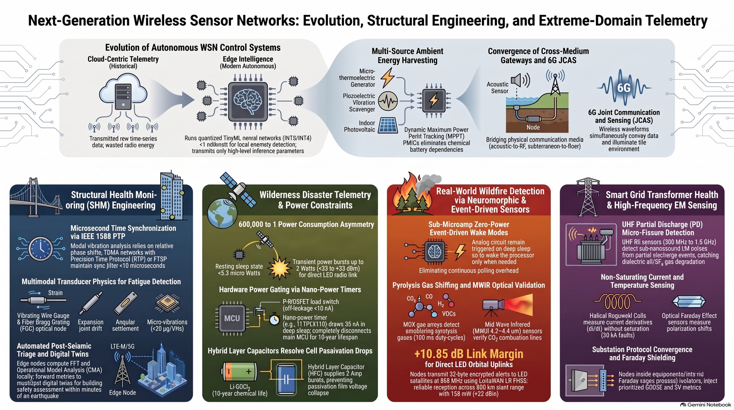
Executive Briefing: Architecture, Engineering Physics, and Domain Implementations of Modern Wireless Sensor Networks (WSNs) and Edge IoT Systems
Executive Summary
The paradigm of the Internet of Things (IoT) and Wireless Sensor Networks (WSNs) has fundamentally shifted from centralized, passive telemetry systems into autonomous, spatially distributed, pervasive physical computing fabrics. Operating at the immediate boundary between physical phenomena and digital intelligence, modern edge systems convert real-world state variables—such as mechanical strain, acoustic pressure, electromagnetic fields, dielectric permittivity, biopotentials, and fluid dynamics—into actionable digital data streams.
The core engineering thesis across all WSN deployments is the simultaneous resolution of three mutually antagonistic operational requirements:
- High-Fidelity Transduction and Signal Conditioning: Capturing weak physical stimuli while suppressing extreme ambient noise, electromagnetic interference (EMI), and common-mode transients.
- Robust Multi-Hop and Long-Range Communications: Transporting data across lossy, non-homogeneous, or physically impenetrable media (including conductive seawater, dense rock strata, high-voltage fields, and thick vegetative canopies).
- Multi-Year Operational Autonomy: Sustaining operations for 5 to 30 years from finite primary electrochemical storage or parasitic energy harvesting, requiring resting power draws down to sub-microampere levels.
Where standard commercial IoT applications prioritize network scalability and low unit cost, industrial and extreme-environment deployments are governed by hard physical constraints. In civil infrastructure, structural health monitoring demands sub-millisecond clock synchronization (<10\ \mu\text{s}) for operational modal analysis. In electric power utilities, nodes must survive common-mode voltage transients (>100\text{ kV}/\mu\text{s}) and harvest power parasitically from magnetic or electric fields. In subterranean mining, high-frequency RF attenuation requires Very Low Frequency (VLF) magnetic induction operating under strict Intrinsic Safety (“Ex ia”) energy boundaries (<150\ \mu\text{J}). In remote wilderness disaster mitigation, deep-sleep power architectures are paired with pulse capacitors (Hybrid Layer Capacitors) to close direct-to-satellite orbital links. In marine systems, electromagnetic absorption forces complete reliance on underwater acoustic propagation (c \approx 1,500\text{ m/s}) subject to severe Doppler shifts and multi-second propagation delays.
- Universal Four-Tier IoT/WSN Architectural Stack
Modern WSNs and Edge IoT platforms adhere to a four-tier operational architecture that systematically decouples low-level transducer physics from enterprise applications.
+————————————————————————————————–+
| TIER 4: APPLICATION & DIGITAL TWIN LAYER |
| – SCADA / Enterprise Historians / Digital Twins / Closed-Loop Control Orchestration |
+————————————————————————————————–+
▲
│ APIs, gRPC, OPC-UA, MQTT
+————————————————————————————————–+
| TIER 3: MIDDLEWARE, FOG & CLOUD PROCESSING LAYER |
| – Stream Ingestion (Kafka) / Device Registries / Over-The-Air (OTA) Firmware Management |
+————————————————————————————————–+
▲
│ IP Backbone, Cellular (5G/NB-IoT), LEO Satellite
+————————————————————————————————–+
| TIER 2: NETWORK & ROUTING LAYER |
| – Deterministic Topologies (TSCH, RPL, 6LoWPAN, LoRaWAN, Wi-SUN, DBR, DTN) |
+————————————————————————————————–+
▲
│ Baseband / Sub-GHz RF / Acoustic / Magnetic
+————————————————————————————————–+
| TIER 1: PERCEPTION & PHYSICAL COMPUTING LAYER (WSN NODE) |
| – Transducers -> Analog Front-End (AFE) -> Digitization (ADC) -> MCU -> Power PMIC -> Radio |
+————————————————————————————————–+
1.1 Hardware Anatomy of an Advanced WSN Node
A WSN edge node comprises five primary functional hardware modules:
+——————-+ +——————-+ +——————-+
| Transducer Array |—->| Signal Conditioning|—->| ADC / MCU Core |
| (Piezo, TDR, CT, | | (IA, Filter, PGA) | | (Cortex-M / RISC-V|
| Acoustic, etc.) | +——————-+ | + DSP + Crypto) |
+——————-+ +———+———+
│
+——————-+ +——————-+ │
| Energy Harvester /|—->| Power Management |───────────────┤
| Battery / HLC | | (PMIC, Load SW, | │
+——————-+ | Nano-Timer) | ▼
+——————-+ +——————-+
| RF Transceiver / |
| Acoustic Modem |
+——————-+
Analog Front-End (AFE) & Signal Conditioning
Raw transducer outputs exhibit microvolt-level amplitudes and high source impedances. Instrumentation Amplifiers (e.g., INA333, AD8421) provide precise differential amplification while suppressing common-mode noise. Differential voltage gain (A_d) and common-mode gain (A_{cm}) define the Common-Mode Rejection Ratio (CMRR): \text{CMRR}{\text{dB}} = 20\log{10}\left(\frac{A_d}{A_{cm}}\right) > 100\text{ dB} Anti-aliasing low-pass active filters (such as 4th-order Butterworth or Bessel topologies) enforce the Nyquist-Shannon sampling limit (f_s \ge 2 f_{\text{max}}) with flat passband characteristics.
Mixed-Signal Digitization
Analog-to-Digital Converters (ADCs) map continuous signals into discrete digital representations. Dynamic range performance is governed by the Effective Number of Bits (ENOB): \text{SNR}_{\text{ideal}} = 6.02 \cdot N + 1.76\text{ dB} \implies \text{ENOB} = \frac{\text{SINAD} – 1.76}{6.02}
- Successive Approximation Register (SAR) ADCs: Deliver 12–16 bit resolutions at sampling rates up to 1 MSPS with zero cycle-latency overhead, optimized for multiplexed, burst-sampled vibration or kinematic sensing.
- Delta-Sigma (\Delta\Sigma) ADCs: Utilize high oversampling ratios (OSR) and noise shaping to achieve 24-bit resolution for low-frequency, high-precision biopotential, strain gauge, or dielectric measurements.
Compute Core
Low-power microcontrollers (MCUs) built on ARM Cortex-M0+/M33 or RISC-V RV32IMAC architectures run at clock speeds between 16 MHz and 80 MHz. They incorporate hardware security engines (AES-128/256, SHA-256, True Random Number Generators), volatile/non-volatile memory (SRAM, FRAM, NOR Flash), and local DSP extensions for executing FFTs or quantized edge machine learning models.
Power Management Subsystem
Integrates buck-boost DC-DC converters achieving >90% conversion efficiency at microampere load currents, paired with high-side P-MOSFET load switches (e.g., TPS22916) for hard power gating (off-state leakage <10\text{ nA}). External nano-power system timers (e.g., TPL5110, drawing \approx 35\text{ nA}) hold the compute core unpowered during deep sleep states.
Transceiver Subsystem
Direct up-conversion RF transceivers operate across Sub-GHz bands (433/868/915 MHz), 2.4 GHz ISM bands, or drive electroacoustic transducers directly in underwater applications.
1.2 Protocol Landscape & Medium Access Control (MAC) Trade-Offs
The choice of Link and MAC protocols determines network determinism, collision probability, and total power overhead:
+—————————————————————————————–+
| MAC Scheme | Latency / Determinism | Energy Efficiency | Throughput / Scalability |
+————-+———————–+——————-+——————————-+
| CSMA/CA | Non-deterministic | Low (Collisions & | Drops rapidly as node count |
| | (Best-effort) | idle listening) | N increases |
+————-+———————–+——————-+——————————-+
| TDMA | Deterministic | High (Scheduled | Rigid; difficult schedule |
| | (Bounded delay) | sleep windows) | maintenance under drift |
+————-+———————–+——————-+——————————-+
| TSCH | Deterministic | Ultra-High | High reliability (>99.999%) |
| (802.15.4e) | (Scheduled hopping) | (Micro-sync) | via 16-channel diversity |
+—————————————————————————————–+
- CSMA/CA (IEEE 802.15.4): Nodes execute Clear Channel Assessment (CCA) before transmitting. Under saturated traffic conditions with N contending nodes, collision probability p approaches 1, causing exponential throughput collapse and battery exhaustion: \eta_{\text{CSMA}} \approx \frac{1}{1 + a \cdot e^{b \cdot N}}
- TSCH (Time-Slotted Channel Hopping): Combines time slots (typically 10\text{ ms}) with pseudo-random channel hopping across 16 channels in the 2.4 GHz band. Absolute Slot Numbers (ASN) dictate the channel assignment formula: f_{\text{channel}} = F\left{(\text{ASN} + \text{ChannelOffset}) \pmod{N_{\text{channels}}}\right} TSCH underpins industrial standards like WirelessHART (IEC 62591) and ISA100.11a (IEC 62734).
- Application & Network Protocols:
- MQTT: TCP-based publish/subscribe protocol with persistent connections, optimized for cloud-to-gateway telemetry but heavy for ultra-constrained nodes.
- CoAP: UDP-based RESTful protocol (RFC 7252) featuring a 4-byte fixed binary header, lightweight request/response semantics, and low overhead over DTLS.
- 6LoWPAN: IPv6 adaptation layer (RFC 6282) providing header compression (down to 2–7 bytes) and fragmentation for IEEE 802.15.4 frames.
- LoRaWAN: Low-Power Wide-Area Network (LPWAN) topology utilizing Chirp Spread Spectrum (CSS) modulation to establish star-of-stars links exceeding 10–15\text{ km}.
- Mainstream Industrial Domain Implementations
+————————————————————————————————–+
| MAINSTREAM APPLICATION DOMAINS |
| |
| Precision Agriculture Transportation & Logistics |
| – Complex dielectric permittivity (Topp Eq.) – Intra-container metallic resonance / attenuation |
| – Canopy attenuation (ITU-R P.833 Sub-GHz) – High-G MEMS vibration logging (ISO 13355) |
| – Sub-GHz LoRaWAN / 802.15.4g topologies – Delay-Tolerant Networking (DTN RFC 5050) |
| |
| Healthcare (WBAN & IoMT) Industrial Process Automation |
| – IEEE 802.15.6 Body Surface Comm – Deterministic TSCH Mesh (WirelessHART/ISA100) |
| – SAR limits (1.6 W/kg) & Tissue Absorption – High-frequency bearing vibration (10–20 kHz) |
| – High-CMRR biopotentials (ECG/PPG/CGM) – Intrinsic safety & explosion-proof bounds |
+————————————————————————————————–+
2.1 Precision Agriculture
Agricultural WSNs monitor real-time soil dynamics, crop microclimates, and sap flow across massive geographic footprints.
- Subsurface Dielectric Profiling: Soil Volumetric Water Content (\theta_v) is measured via Time-Domain Reflectometry (TDR) or Frequency-Domain Reflectometry (FDR). Because liquid water has a high dielectric constant (\varepsilon_r \approx 80) compared to dry soil minerals (\varepsilon_r \approx 3–5) and air (\varepsilon_r \approx 1), electromagnetic wave velocity v = c / \sqrt{\varepsilon_r’} reveals water concentration. \theta_v is calculated using Topp’s Equation: \theta_v = -0.053 + 0.0292\varepsilon_r’ – 5.5 \times 10^{-4}(\varepsilon_r’)^2 + 4.3 \times 10^{-6} (\varepsilon_r’)^3
- Canopy Path Loss Modeling: Crop foliage attenuates high-frequency signals via water resonance and multi-path scattering. Canopy path loss follows the Modified ITU-R P.833 model: A_{\text{canopy}} = a \cdot f^b \cdot (1 – e^{-d \cdot c}) \quad [\text{dB}] At 2.4 GHz, canopy absorption rates reach 1.5–4.5\text{ dB/m}, making Sub-GHz frequencies (868/915 MHz, attenuation 0.2–0.8\text{ dB/m}) mandatory.
- Transducers & Actuation: Employs Ion-Selective Field-Effect Transistors (ISFETs) for nitrate/potassium tracking, non-contact infrared pyrometers for canopy temperature, and Granier-type sap flow thermal sensors. Closed-loop systems interface with Variable Rate Irrigation (VRI) solenoids and fertigation injection pumps.
2.2 Transportation & Cold Chain Logistics
Logistics networks ensure product integrity across global transit corridors.
- Cold Chain Auditing: Uses high-precision PT100/PT1000 Resistance Temperature Detectors (\pm 0.1^\circ\text{C} accuracy) for cryogenic monitoring (down to -196^\circ\text{C} in liquid nitrogen dry shippers), paired with Non-Dispersive Infrared (NDIR) sensors to log ethylene (C_2H_4) and CO_2 gas buildup in refrigerated containers (reefers).
- Mechanical Shock & Tamper Logging: Tri-axial MEMS accelerometers (e.g., ADXL355) sample continuously at 1–4 kHz, calculating Power Spectral Density (PSD, \text{g}^2/\text{Hz}) and peak g-force under ISO 13355 standards. Optical photodiodes detect micro-lumen light breaches if container doors are opened.
- Faraday Cage Mitigation & DTN: Steel container walls induce 40–60\text{ dB} of RF attenuation at 2.4 GHz. Internal nodes form dynamic mesh networks (e.g., Wirepas, BLE Mesh) to route data to door pass-through antennas. When external connectivity is lost, Delay-Tolerant Networking (DTN / Bundle Protocol RFC 5050) caches cryptographically signed logs locally until docking at a gateway terminal.
2.3 Healthcare & Wireless Body Area Networks (WBANs)
Healthcare IoT demands continuous biopotential sensing without exposing biological tissue to excessive RF energy or thermal stress.
- IEEE 802.15.6 Standard: Engineered for body-centric communications, supporting Narrowband (NB: 402–405 MHz MedRadio, 863–870 MHz, 2.4 GHz), Ultra-Wideband (UWB: 3.1–10.6 GHz), and Human Body Communication (HBC: capacitive coupling through tissue at 10–50 MHz).
- Specific Absorption Rate (SAR) Limits: RF energy absorption by biological tissue is strictly bounded (1.6 W/kg averaged over 1 g of tissue in the US), limiting transmit power levels to \le -10\text{ dBm} to 0\text{ dBm}.
- Sensing Modalities:
- Biopotential Front-Ends: ECG, EEG, and EMG acquisition circuits use instrumentation amplifiers with \text{CMRR} > 100\text{ dB}, Right-Leg Drive (RLD) noise cancellation, and dry Ag/AgCl or capacitive electrodes.
- Photoplethysmography (PPG): Emits dual-wavelength light (660 nm red, 940 nm IR) to calculate peripheral capillary oxygen saturation (\text{SpO}_2) and arterial pulse wave velocity.
- Continuous Glucose Monitors (CGM): Enzymatic micro-needles inserted into subcutaneous interstitial fluid stream real-time glucose metrics to automated insulin patch-pumps.
- Biocompatibility: Housings utilize non-thrombogenic, non-toxic materials like Parylene-C, medical-grade silicone, and Grade 5 titanium.
2.4 Industrial Controls & Process Automation
Industrial WSNs (IWSNs) prioritize deterministic real-time latency and extreme reliability over data throughput in dense, highly reflective plant environments.
- Standards & Network Fabric: Deploy WirelessHART (IEC 62591) and ISA100.11a (IEC 62734) running TSCH over IEEE 802.15.4 hardware. Network Managers maintain dual-independent routing paths for every node, delivering >99.999% (“five nines”) packet reliability with microsecond-level time synchronization (<10\ \mu\text{s}).
- Predictive Maintenance (Condition-Based Monitoring – CBM): Piezoelectric and high-bandwidth MEMS accelerometers sample bearing vibrations at 10–25 kHz. Compute cores execute local Fast Fourier Transforms (FFTs) and envelope demodulation to extract feature vectors (identifying Ball Pass Frequency Outer/Inner race degradation) and transmit anomaly metrics rather than raw time-series data.
- Hazardous Environments & Intrinsic Safety: Equipment operating in explosive atmospheres (ATEX/IECEx Zone 0/1) incorporates energy-limiting barriers, galvanic isolation, and explosion-proof enclosures.
- Extreme Domain Implementations: Engineering at Physical Boundaries
+—————————————————————————————————-+
| EXTREME PHYSICAL BOUNDARY DOMAINS |
| |
| Electric Power Utilities (HV/EHV/UHV) Underground Mining & Subsurface |
| – Bird-on-a-wire equipotential enclosure – VLF/ELF magnetic induction (300 Hz – 3 kHz) |
| – Waveguide-Below-Cutoff (WBC) apertures – Intrinsic Safety “Ex ia” Group I (IEC 60079-11) |
| – High CMTI (>150 kV/µs) isolation – Methane spark limits (<150 µJ energy, 150°C temp)|
| – Parasitic CT magnetic & E-field harvesting – Series-resonant LC coils & Zener barriers |
| |
| Remote Wilderness Disaster Mitigation Marine & Underwater Acoustic Networks (UWSNs) |
| – Hard power gating (TPL5110 timer, 35 nA) – Acoustic propagation (c ≈ 1,500 m/s) |
| – Li-SOCl2 passivation & HLC capacitor buffer – SOFAR waveguide refraction & Thorp absorption |
| – Direct-to-Satellite IoT (LR-FHSS, NTN) – Tonpilz piezoceramic transducers & ZP-OFDM |
| – Positive orbital link budget (+11.35 dB) – Titanium Grade 5 hulls (10 MPa/km) & Depth-Based |
| Routing (DBR) |
+—————————————————————————————————-+
3.1 High-Voltage Electric Power Utilities (69 kV to 1,100 kV)
Deploying sensors directly onto energized transmission conductors or switchgear presents an extreme electromagnetic environment characterized by high quasi-static field gradients, high-energy switching transients, and corona discharge.
+—————————————————————————————+
| Outer Equipotential Enclosure (Cast Aluminum / Alodine-finished Al-6061) |
| +——————————————————————————-+ |
| | Rounded Corona Ring Geometry (R_edge > 15 mm) | |
| | Waveguide-below-cutoff vents (d < lambda/10) | |
| | | |
| | Inner Magnetic Shield: High-Permeability Mu-Metal (Mu_r > 50,000) | |
| | +————————————————————————-+ | |
| | | Multi-Layer PCB Ground Plane Architecture | | |
| | | – Galvanic Isolation (CMTI > 150 kV/µs) | | |
| | | – Multi-Stage Transient Clamping: GDT -> Hybrid Choke -> Low-Cap TVS | | |
| | +————————————————————————-+ | |
| +——————————————————————————-+ |
+—————————————————————————————+
Shielding & Enclosure Physics
Nodes mounted directly to energized conductors operate on the “bird-on-a-wire” equipotential principle. However, transient high-frequency events create steep differential potential gradients (V_{\text{diff}} = L_{\text{body}} \cdot \frac{di}{dt}).
- Enclosure Material: A cast aluminum shell (e.g., Alodine-finished 6061-T6, 3 mm thick) provides high electrical conductivity (\sigma \approx 3.8 \times 10^7\text{ S/m}). At 100 MHz (Very Fast Transients in Gas-Insulated Switchgear), the skin depth is \delta \approx 8.2\ \mu\text{m}, yielding >100\text{ dB} of high-frequency absorption shielding: A_{\text{dB}} \approx 8.686 \cdot \frac{t}{\delta} = 8.686 \cdot t \sqrt{\pi f \mu \sigma}
- Low-Frequency Magnetic Shielding: High-frequency aluminum shells are transparent to 60 Hz magnetic fields (\mu_r \approx 1). Secondary inner shields constructed from high-permeability Mu-metal (\mu_r \ge 50,000) shunt low-frequency magnetic flux away from sensitive analog traces to prevent ADC drift.
- Corona Mitigation: Outer enclosure geometries maintain edge radii R_{\text{edge}} > 15–20\text{ mm} to prevent localized surface electric field gradients from exceeding the dielectric breakdown threshold of air (E_0 \approx 30\text{ kV/cm}), suppressing corona ionization and broad-spectrum RFI (100 kHz–1 GHz).
- Waveguide-Below-Cutoff (WBC): Penetrations for airflow or non-metallic sensors use metallic tubes with diameter d and length \ell. Operating below the cutoff frequency f_c = \frac{175.7}{d\text{ (mm)}}\text{ GHz}, electromagnetic waves attenuate exponentially: \alpha_{\text{dB}} \approx 27.3 \cdot \frac{\ell}{d} Maintaining \ell/d \ge 3 delivers >80\text{ dB} of attenuation across the GHz spectrum.
- Circuit Hardening: Signal lines exposed to high transient voltage slew rates incorporate digital isolators providing Common-Mode Transient Immunity (\text{CMTI} \ge 150–200\text{ kV}/\mu\text{s}) with parasitic barrier capacitance <0.2\text{ pF}. Sensor inputs employ three-stage protection: Gas Discharge Tubes (GDTs) \to decoupling chokes \to fast bidirectional TVS diodes.
Parasitic Energy Harvesting Topologies
To operate indefinitely without batteries, nodes harvest energy directly from surrounding fields:
+—————————————————————————————–+
| Magnetic Harvesting (CT) |
| Conductor Current (10 A – 40 kA) ──> Nanocrystalline Core (Split) ──> Secondary Current |
| ──> Active Depletion MOSFET Shunt / Triac Crowbar ──> Active Rectifier ──> PMIC |
| |
| Electric-Field Harvesting (Capacitive) |
| Line Voltage (69 kV – 765 kV) ──> Outer Harvesting Shell ──> Stray Cap to Earth (1-50 pF)|
| ──> High-Voltage Diode Bridge ──> Synchronous Charge Extraction Switch ──> Buck PMIC |
+—————————————————————————————–+
- Inductive Current Harvesting (Magnetic Field): Split-core Current Transformers (CTs) wrapped around the phase conductor extract power via Faraday’s Law (V_s = -N A_e \frac{dB}{dt}). High-permeability nanocrystalline core materials (Finemet/Vitroperm, \mu_i \ge 20,000, B_{\text{sat}} \approx 1.2\text{ T}) enable startup at low conductor currents (<10–15\text{ A}).
- The Fault-Current Dilemma: A short-circuit fault (I_{\text{fault}} \ge 20–40\text{ kA}) induces a catastrophic I^2 energy surge (9,000,000:1 ratio over a 10 A baseline).
- Mitigation: Active depletion-mode MOSFET shunt arrays monitor the secondary voltage rail. When storage capacitors reach full capacity or secondary currents exceed safety limits, the MOSFETs short the CT secondary winding. This creates a counter-EMF that forces core flux into a virtual short-circuit condition, restricting heat dissipation to I_s^2 \cdot R_{DS(\text{on})}. Fast bidirectional Triac crowbars serve as solid-state fallbacks for nanosecond transient protection.
- Capacitive Displacement Harvesting (Electric Field): Conductive sleeves suspended in air form a capacitive voltage divider between the high-voltage conductor and remote earth ground (C_{\text{ground}} \approx 1–50\text{ pF}). The harvested displacement current density is: I_{\text{harvest}} = \int \mathbf{J}D \cdot d\mathbf{A} = \omega C{\text{ground}} V_{\text{line}} At 115\text{ kV}, a 10\text{ pF} stray capacitance yields I_{\text{harvest}} \approx 250\ \mu\text{A}. Because the source impedance is high (|Z_C| \approx 265\text{ M}\Omega at 60 Hz), high-voltage full-wave diode bridges feed intermediate buffer capacitors (C_{\text{in}} \approx 100\text{ nF}). When V_{C\text{in}} reaches 150–300\text{ V}, ultra-low-power comparators trigger a high-voltage GaN/SiC switch, discharging the energy in short pulses through a high-frequency buck converter to a 3.3 V rail at >85% efficiency.
3.2 Subsurface Mining Operations & Geotechnical Engineering
Underground mining environments present two major physical hazards: high electromagnetic wave attenuation through rock and explosive atmospheres caused by firedamp (methane, \text{CH}_4) and suspended coal dust.
+————————————————————————————————–+
| Hazardous Area (Ex ia Zone 0) Safe / Protected Area |
| =========================== =================== |
| Transducer Interface Zener Barrier Network |
| – Borehole Inclinometer – Redundant Zener Diodes (Triple Redundant) |
| – CH4 Infrared Sniffer – Series Current-Limiting Resistors |
| – Fast-Blow Ceramic Fuse |
| │ │ |
| ▼ ▼ |
| [ Sensor Signal ] ──> [ Creepage Clearance ] ──> [ 3x Zener ] ──[ Resistor ]──[ Fuse ]──> ADC |
| (Distance ≥ 10 mm) (Clamps V) (Limits I) |
| |
| Mechanical Containment: Solid Encapsulation (≥3 mm) / Anti-Static Polymer (≤1 GΩ) |
+————————————————————————————————–+
Through-The-Earth (TTE) Propagation Physics
High-frequency radio signals suffer severe attenuation (\alpha) in lossy geological strata (\sigma \approx 10^{-3}–10^{-1}\text{ S/m}): \alpha = \sqrt{\frac{\omega\mu\sigma}{2}} = \sqrt{\pi f \mu \sigma} \quad [\text{Nepers/m}] \implies \text{Attenuation}{\text{dB/m}} \approx 8.686 \sqrt{\pi f \mu \sigma} At 915 MHz, attenuation through damp sandstone exceeds 1,200\text{ dB/m}, absorbing signals within centimeters. TTE systems drop carrier frequencies to the Voice-Frequency / Very Low Frequency (VLF: 300 Hz–3 kHz) regime. At 1 kHz, attenuation drops to \approx 0.054\text{ dB/m}, allowing quasi-magnetostatic fields generated by magnetic dipoles (m = N I A) to penetrate hundreds of meters of solid overburden: |B_r(r)| = \frac{\mu_0 m}{2 \pi r^3} \sqrt{1 + \frac{2r}{\delta} + 2\left(\frac{r}{\delta}\right)^2} \cdot e^{-r/\delta} where \delta = 1/\sqrt{\pi f \mu \sigma} is the skin depth. Receiver nodes utilize ferrite-cored coils (A{\text{effective}} = A_{\text{geometric}} \cdot \mu_{\text{rod}}) and DSSS modulation to extract signals buried 10–20\text{ dB} beneath ambient heavy-machinery EMI floors.
Principles of Intrinsic Safety (“Ex ia” Group I)
In coal and metal mines, standard explosion-proof enclosures (“Ex d”) are often too heavy and costly for distributed WSN nodes. Sensor nodes instead employ Intrinsic Safety (“Ex ia” / IEC 60079-11), which limits electrical and thermal energy to levels below those that can ignite methane or coal dust.
- Methane Ignition Physics: A stoichiometric methane-air mixture (9.5%\ \text{CH}4) exhibits a Minimum Ignition Energy (MIE) of 0.28\text{ mJ} (280\ \mu\text{J}). Under Ex ia Group I mandates (safe under normal operation plus two independent faults, with a 1.5\times safety factor), maximum allowed spark energy storage is capped at: E{\text{capacitive}} = \frac{1}{2} C V^2 \le 150\ \mu\text{J}, \quad E_{\text{inductive}} = \frac{1}{2} L I^2 \le 150\ \mu\text{J}
- Thermal Limits: Maximum component surface temperatures must not exceed 150^\circ\text{C} under worst-case fault conditions to prevent coal dust layer auto-ignition.
- Resolving the Power Contradiction via Series Resonance: Driving magnetic TTE antennas demands high magnetic moments (m = N I A), which conflicts with inductive energy bounds (E = \frac{1}{2} L I^2). Transmitters resolve this by placing safety-certified capacitors (C_{\text{res}}) in series with the antenna loop (L_{\text{ant}}), tuning the network to exact carrier resonance (\omega_0 = 1/\sqrt{L_{\text{ant}} C_{\text{res}}}). At resonance, inductive and capacitive reactances cancel, leaving only low winding resistance (R_s \approx 0.5–2.0\ \Omega). Safe low-voltage rails (V \le 5\text{ V}) can drive oscillating currents of several amperes through the coil without violating DC voltage bounds. Inverse-parallel flyback diode arrays clamp inductive collapse energy if antenna wires break.
- Ex ia Circuit Protection & PCB Rules:
- Zener Barriers: Incorporate fast-acting ceramic fuses, triple-redundant parallel Zener diodes (to clamp overvoltages), and series metal-oxide resistors (to limit short-circuit currents).
- Creepage & Clearance: Strict physical spacing rules govern trace separation on unpotted PCBs:
+———————————————————————————–+
| Peak Voltage (V_peak) | Min. Air Clearance (Ex ia) | Min. Creepage in Air (Ex ia) |
+———————–+—————————-+——————————+
| ≤ 10 V | 1.5 mm | 1.5 mm |
| ≤ 30 V | 2.0 mm | 3.0 mm |
| ≤ 60 V | 3.0 mm | 4.0 mm |
+———————————————————————————–+
Solid polyurethane encapsulation (potting depth $\ge 3\text{ mm}$) lowers spacing bounds to sub-millimeter scales.
- Battery Module Hardening: Utilizes inherently stable Lithium Iron Phosphate (\text{LiFePO}_4) cells (thermal runaway threshold >270^\circ\text{C}). Modules are encapsulated with non-resettable thermal fuses (85^\circ\text{C} blow point) and integrated current-limiting resistors. Enclosures incorporate anti-static additives to enforce surface resistivity \le 1\text{ G}\Omega to prevent ESD.
- Spark Test Qualification: Certification requires zero ignitions across thousands of make-and-break contact sparks inside an explosion chamber filled with an 8.3%\ \text{CH}_4 test gas mixture.
3.3 Remote Wilderness Disaster Mitigation
Wilderness environmental monitoring (flash floods, wildfires, volcanic unrest, landslips) requires multi-year autonomy without terrestrial cellular infrastructure or solar availability under dense tree canopies.
+—————————————————————————————————-+
| [ PRIMARY POWER SUPPLY ] |
| Li-SOCl2 Cell (3.6 V, 19 Ah) ──┬──> [ Hybrid Layer Capacitor (HLC 1550) ] ─> Main Switched Rail |
| │ |
| └──> [ Ultra-Low Iq Step-Down Buck ] (Quiescent Current = 60 nA) |
| │ |
| ▼ (Regulated 2.5 V Always-On) |
| [ WAKE CONTROL & ASYNCHRONOUS LOGIC ] |
| ├── Nano-Timer (TPL5110) [35 nA] ──────────────────────────────────────────┐ |
| └── Dual-Axis Nano-Comparator (TLV7031) [300 nA] ──(Trip Threshold) ──────┤ |
| │ |
| ▼ |
| [ LOAD GATING SWITCHES ] <────────────────────────────────────── Assert System Power |
| TPS22916 Load Switches (Off-state leakage = 10 nA) |
| ├── System Power Switch A ──> Microcontroller Core (ARM Cortex-M33 @ 24 MHz) |
| ├── System Power Switch B ──> Disaster Sensor Array Front-End |
| └── System Power Switch C ──> Satellite Transceiver + Front-End RF Module |
+—————————————————————————————————-+
Deep-Sleep Micro-Watt Power Architectures
To achieve a 10-year lifespan on a standalone battery, baseline resting current (I_{\text{sleep}}) must stay below 1.5\ \mu\text{A}: I_{\text{avg}} = \frac{t_{\text{active}} \cdot I_{\text{active}} + t_{\text{sleep}} \cdot I_{\text{sleep}}}{t_{\text{active}} + t_{\text{sleep}}}
- Hardware Power Gating: Rather than relying on MCU software standby states (which risk cosmic-ray latch-up freezing), systems use high-side P-MOSFET load switches (leakage <10\text{ nA}) to physically disconnect power from MCU cores, sensors, and radios.
- Nano-Power Timers & Asynchronous Wake: An external timer (TPL5110, drawing 35\text{ nA}) counts down sleep intervals. In parallel, ultra-low-power analog comparators (drawing 300\text{ nA}) evaluate passive transducers (e.g., zero-bias electrochemical gas sensors or piezoelectric geophones) to trigger instant system interrupts when physical thresholds are breached.
Battery Chemistry & The Passivation Solution
Primary Lithium Thionyl Chloride (\text{Li-SOCl}_2) bobbin cells are selected for their high gravimetric energy density (>650\text{ Wh/kg}) and wide operational temperature range (-60^\circ\text{C} to +85^\circ\text{C}).
- The Passivation Problem: \text{Li-SOCl}2 forms a protective Lithium Chloride (\text{LiCl}) crystalline film on its lithium anode, limiting self-discharge to <1% per year. However, this passivation layer acts as a high internal resistance barrier. When a satellite transceiver fires, demanding a 1–2 A pulse, the cell voltage drops instantly: V{\text{terminal}} = V_{\text{OCV}} – I_{\text{pulse}} \cdot R_{\text{passivation}} In cold temperatures, voltage can collapse below 2.0\text{ V}, triggering MCU brownout resets before transmission completes.
- The Hybrid Layer Capacitor (HLC) Solution: A pulse-density Hybrid Layer Capacitor (low ESR <100\text{ m}\Omega) is wired in parallel with the bobbin cell. The \text{Li-SOCl}_2 cell continuously trickle-charges the HLC. When the radio fires, the low-ESR HLC delivers the entire 2 A current pulse, maintaining rail voltage above 3.3\text{ V} and preserving the primary cell’s passivation layer.
Direct-to-Satellite IoT Link Budgets
Sensors transmit telemetry directly to Low-Earth Orbit (LEO, 500–1,200 km altitude) satellites using low-power radios.
+————————————————————————————+
| Empirical Link Budget: Sub-GHz Link to LEO Satellite (868 MHz @ 800 km Slant Range)|
+————————————————————————————+
| Transmit Power (P_tx) | +22.00 dBm (158 mW) |
| Transmit Antenna Gain (G_tx) | +2.15 dBi (Omnidirectional Dipole) |
| Free Space Path Loss (FSPL) | -149.30 dB (800 km distance) |
| Atmospheric & Rain Loss (L_atm) | -0.50 dB |
| Polarization Mismatch Loss (L_pol) | -3.00 dB (Linear to RHCP) |
| Ionospheric Scintillation Margin | -3.00 dB |
| Satellite Receive Antenna Gain (G_rx) | +6.00 dBi (Phased Array) |
+————————————————————————————+
| Total Received Power (P_rx) | -125.65 dBm |
| Noise Floor (N, 125 kHz Bandwidth) | -134.00 dBm |
| Satellite Receiver Sensitivity | -137.00 dBm (LR-FHSS Modulation) |
+————————————————————————————+
| RESULTING LINK MARGIN | +11.35 dB (Reliable Link Closed) |
+————————————————————————————+
\text{FSPL}{\text{dB}} = 20\log{10}(d) + 20\log_{10}(f) + 20\log_{10}\left(\frac{4\pi}{c}\right) \approx \mathbf{149.28\text{ dB}} Because the net link margin is positive (+11.35\text{ dB}), a 158\text{ mW} ground node successfully closes the orbital link using omnidirectional antennas.
- Modulation Technologies:
- LR-FHSS (Long Range Frequency Hopping Spread Spectrum): Splits payloads into small fragments, hopping across hundreds of narrow frequency sub-channels (488\text{ Hz} wide). This yields high Doppler immunity against fast-moving LEO satellites (7.5\text{ km/s}) and high collision resistance.
- 3GPP Rel-17/18 IoT-NTN (Non-Terrestrial Networks): Adapts NB-IoT/LTE-M waveforms to directly communicate with satellites, pre-compensating baseband processing for Doppler shifts (\pm 35–40\text{ kHz}) and propagation delays (>25\text{ ms}).
Mathematical 10-Year Lifecycle Calculation
For an alpine flood-monitoring node running on a single 19\text{ Ah}\ \text{Li-SOCl}_2 D\text{-cell} with an HLC:
- Deep Sleep (99.96% duty cycle): 0.41\ \mu\text{A} \times 24\text{ h} \times 365\text{ d} \times 10\text{ yr} = \mathbf{35.9\text{ mAh}}
- Hourly Radar Interrogation (0.5\text{ s} @ 18\text{ mA}): 0.060\text{ mAh/day} \times 3650\text{ d} = \mathbf{219.0\text{ mAh}}
- Twice-Daily Satellite Uplink (10\text{ s} @ 130\text{ mA}): 0.722\text{ mAh/day} \times 3650\text{ d} = \mathbf{2,635.3\text{ mAh}}
- Cumulative Operational Consumption: 35.9 + 219.0 + 2635.3 = \mathbf{2,890.2\text{ mAh}}\ (2.89\text{ Ah})
- Derating (10% self-discharge over 10 years = 1.90\text{ Ah}): Total capacity used = \mathbf{4.79\text{ Ah}}.
\text{Capacity Safety Margin} = \frac{19.0\text{ Ah} – 4.79\text{ Ah}}{19.0\text{ Ah}} \times 100% = \mathbf{74.8%\ \text{Remaining Capacity}}
3.4 Marine Systems & Underwater Acoustic Sensor Networks (UWSNs)
High salinity causes seawater to act as a conductive medium (\sigma \approx 4\text{ S/m}), attenuating radio waves within centimeters (\text{RF Attenuation} \propto \sqrt{\omega \mu \sigma}). Optical links scatter rapidly in non-clear water, restricting communications to <10–30\text{ m}. Consequently, UWSNs use mechanical sound waves as their primary transmission medium.
Depth (z) 0 m ┌──────────────────────────────────────────────┐
│ Surface Mixed Layer (Isothermal / Wind-Mixed)│
├──────────────────────────────────────────────┤
│ THERMOCLINE │
│ (Steep Velocity Drop) │
1000 m├──────────────────────────────────────────────┤ ◄── SOFAR Channel Axis
│ DEEP ISOTHERMAL │
│ (Pressure Increase Dominates) │
│ Sound Speed Increases with Depth │
4000 m└──────────────────────────────────────────────┘
1480 m/s 1500 m/s 1540 m/s ──> Sound Speed (c)
Physical Acoustics & Propagation Mechanics
- Sound Speed Profile (SVP): Sound speed c varies with temperature T, salinity S, and depth z per the Mackenzie Equation: c(T, S, z) = 1448.96 + 4.591T – 5.304 \times 10^{-2}T^2 + 2.374 \times 10^{-4}T^3 + 1.340(S – 35) + 1.630 \times 10^{-2}z + \dots Refraction obeys Snell’s Law (\cos \theta(z) / c(z) = \text{constant}). Rays continuously bend toward regions of minimum sound speed, forming the SOFAR (Sound Fixing and Ranging) Channel at 800–1,200\text{ m} depth. This layer acts as a waveguide, propagating sound over thousands of kilometers.
- Propagation Delay & Absorption: Sound travels at \approx 1,500\text{ m/s} (0.67\text{ s/km} propagation delay—five orders of magnitude slower than light). Total Transmission Loss (TL) over distance R (meters) for frequency f (kHz) incorporates geometric spreading (k=1.5) and medium absorption (\alpha): \text{TL} = k \cdot 10\log_{10}(R) + \alpha(f) \cdot R \times 10^{-3} \quad [\text{dB}] Absorption \alpha(f) (in dB/km) follows Thorp’s Formula, driven by chemical relaxation of boric acid (<1\text{ kHz}), magnesium sulfate (1–50\text{ kHz}), and viscous water losses (>50\text{ kHz}): \alpha(f) \approx \frac{0.11 f^2}{1 + f^2} + \frac{44 f^2}{4100 + f^2} + 2.75 \times 10^{-4} f^2 + 0.003 At f=50\text{ kHz}, absorption is \approx 15\text{ dB/km}; at f=2\text{ kHz}, absorption drops to \approx 0.12\text{ dB/km}. Long-range UWSNs (>10\text{ km}) are restricted to frequencies below 5\text{ kHz}, yielding usable channel bandwidths of only a few hundred hertz.
- Doppler Scaling: Relative motion causes wideband Doppler scaling (\Delta = v/c). A relative velocity of 1.5\text{ m/s} yields \Delta = 10^{-3}, dilating acoustic waveforms and destroying subcarrier orthogonality in standard OFDM.
Transducer Architecture & Modulation
- Tonpilz Piezoelectric Projector: Incorporates a stack of prestressed piezoceramic rings (PZT-4 or PZT-8) operating in longitudinal expansion mode (d_{33}). A central high-tensile steel bolt places the stack under 20–40\text{ MPa} mechanical compression to prevent tension fracturing. A flared lightweight head mass (aluminum/titanium) matches seawater acoustic impedance (Z_{\text{water}} \approx 1.5 \times 10^6\text{ Rayls}), while a heavy tail mass (tungsten/brass) focuses energy forward.
+————————————————————————————————-+
| [ Heavy Tail Mass ] [ Piezoceramic Ring Stack ] [ Flared Head Mass ] |
| (Tungsten / Steel) (Prestressed PZT-4 / PZT-8) (Aluminum / Magnesium) |
| +—————+ +————————-+ +——————-+ |
| | |══════════| [PZT] [PZT] [PZT] [PZT] |══════════| \ Water |
| | | ▲ | | ▲ | | Medium|
| +—————+ │ +————————-+ │ +——————-/ |
| └──────── Central Pre-Stress Bolt ───┘ |
+————————————————————————————————-+
- Acoustic Modulation:
- MFSK: Uses guard bands to allow multipath echoes (10–100\text{ ms} delay spreads) to decay, yielding robust but low-rate links (100–1,200\text{ bps}).
- Zero-Padded OFDM (ZP-OFDM): Replaces continuous cyclic prefixes with null guard intervals to eliminate inter-block interference. Receivers apply time-domain resampling to remove bulk Doppler scaling before carrier decoding.
- Acoustic MAC & Routing: Terrestrial CSMA fails underwater due to multi-second propagation delays. UWSNs use Slotted Floor Acquisition Multiple Access (S-FAMA), T-Lohi, or Spatial-Temporal TDMA (ST-TDMA). Routing relies on Depth-Based Routing (DBR): nodes read their depth via hydrostatic pressure sensors and dynamically forward packets to shallower candidate nodes. Candidates set holding time delays (t_{\text{hold}} = \tau_{\text{max}} \cdot (1 – \Delta z / R_{\text{range}})) so the shallowest node retransmits first, naturally suppressing redundant uplinks.
Mechanical Sizing & Biofouling Hardening
Hydrostatic pressure increases by \approx 0.1013\text{ MPa} (1\text{ atm}) per 10.06\text{ m} of depth (reaching 40\text{ MPa} / 5,800\text{ psi} at 4,000\text{ m}).
- Pressure Hulls: Machined from Grade 5 Titanium (Ti-6Al-4V, yield strength \sigma_y \approx 830\text{ MPa}) or Polyether Ether Ketone (PEEK). Walls are sized against elastic buckling and yield limits: t_{\text{yield}} \approx \frac{P_{\text{ext}} \cdot D_o}{2\sigma_y \cdot \text{SF}} Dual radial Buna-N or Viton O-rings (70 to 90 durometer) with backup rings ensure hermetic sealing.
- Biofouling Control: Marine biofouling clogs conductivity cells and alters transducer resonance. Systems use Copper-Nickel (CuNi 90/10) housings, vacuum-encapsulated acoustic polyurethanes, and pulsed Deep-UV (UV-C LEDs, 265–280 nm) irradiation to disrupt bacterial biofilms.
- Case Study (DART Tsunami Warning): Benthic bottom pressure recorders monitor hydrostatic pressure via vibrating quartz crystals. If an ocean wave shift exceeds 3\text{ cm}, the node switches from low-duty check-ins to emergency mode, transmitting acoustic bursts (185\text{ dB re } 1\ \mu\text{Pa}) through 6,000\text{ m} of water to a surface buoy, which relays alerts to emergency networks via satellite within minutes.
- Cross-Domain Comparative Analysis
+—————————————————————————————————————————————+
| Domain / Parameter | Transmission Medium | Time Sync Requirement | Dominant Standards | Primary Energy Model | Dominant Constraint |
+———————+———————–+———————–+———————+————————-+————————+
| Structural Health | Sub-GHz RF, 2.4 GHz, | Sub-millisecond | IEEE 1588 (PTP), | Solar, Ambient | Concrete/steel RF |
| Monitoring (SHM) | 5.8 GHz Mesh, Fiber | (< 10 µs) | TDMA Mesh, 5G | Vibration Harvesting | masking, clock drift |
+———————+———————–+———————–+———————+————————-+————————+
| Smart Grid & Power | Sub-GHz FHSS, Wi-SUN, | Microsecond | Wi-SUN, IEC 61850, | Parasitic CT / E-Field | Extreme EMI, transient |
| Utilities | Fiber, 2.4 GHz | (< 1 µs) | C37.118, GOOSE | Harvesting, LTO Battery | surges, high dV/dt |
+———————+———————–+———————–+———————+————————-+————————+
| Mining & Subsurface | Low-Freq VLF Induction| Low | Intrinsic Safety | Primary Cells, | Rock attenuation, |
| Geotechnical | (300Hz-3kHz), Leaky RF| (1 – 10 s) | Ex ia, ATEX, MSHA | IS-limited Power Rails | explosion risk (CH4) |
+———————+———————–+———————–+———————+————————-+————————+
| Wilderness Disaster | Sub-GHz, Satellite | Medium | LoRaWAN LR-FHSS, | Li-SOCl2 + HLC, | Extreme canopy loss, |
| Mitigation | LEO (L/S band) | (100 ms) | 3GPP Rel-17 NTN | Micro-watt Deep Sleep | zero infrastructure |
+———————+———————–+———————–+———————+————————-+————————+
| Marine & Subsea | Acoustic Wave Links | Very Low | Proprietary Acoustic| Large Li-SOCl2 Bank, | Slow propagation delay,|
| Systems (UWSNs) | (10 kHz – 50 kHz) | (Asynchronous) | Stacks, DBR Routing | Wave / Microbial Fuel | biofouling, pressure |
+———————+———————–+———————–+———————+————————-+————————+
| Precision | Sub-GHz RF (868/915), | Low | LoRaWAN, 802.15.4g, | Primary LiFePO4, | Crop canopy loss, |
| Agriculture | NB-IoT, Satellite | (Seconds) | Wi-SUN | Micro Solar Photovoltaic| soil variable salinity |
+———————+———————–+———————–+———————+————————-+————————+
| Transportation & | 2.4 GHz Mesh, BLE, | Medium | Wirepas, C-V2X, | Primary Cell, | Metallic attenuation |
| Logistics | Cellular, Satellite | (Minutes / DTN) | DTN (RFC 5050) | ISO 13355 Shock Logging | (Faraday cage), shifts |
+———————+———————–+———————–+———————+————————-+————————+
| Healthcare | MedRadio (402-405MHz),| Medium | IEEE 802.15.6, | Body Energy Harvesting, | Tissue SAR limits, |
| (WBAN / IoMT) | BLE, UWB (3.1-10.6GHz)| (Milliseconds) | BLE GATT Profiles | Coin Cell | biocompatibility |
+———————+———————–+———————–+———————+————————-+————————+
| Industrial Automation| 2.4 GHz TSCH, Sub-GHz | High Precision | WirelessHART, | Vibration Harvesting, | Multipath reflections, |
| (IWSNs) | Mesh | (< 10 µs) | ISA100.11a, TSCH | Process Thermal TEG | high EMI, brownfields |
+—————————————————————————————————————————————+
- Strategic Frontiers & Future Outlook
Three cross-cutting technological trends are shaping the future of autonomous edge sensing fabrics:
+————————————————————————————————–+
| NEXT-GENERATION EDGE INNOVATIONS |
| |
| 1. TinyML & Neuromorphic Edge Compute |
| – Micro-watt event-driven inference engines running quantized neural networks (INT8/INT4). |
| – Filters false alarms at the sensor, reducing RF airtime and power draw by 10–100×. |
| |
| 2. Multi-Source Ambient Energy Harvesting & Battery-Free Nodes |
| – Hybrid Piezoelectric-TEG-Photovoltaic energy scavengers. |
| – Ultra-low cold-start PMICs (<20 mV) enable multi-decade maintenance-free operation. |
| |
| 3. Hardware-Enforced Zero-Trust Security & Silicon Roots of Trust |
| – Silicon PUFs (Physical Unclonable Functions) and hardware crypto acceleration engines. |
| – Protects resource-constrained nodes against tampering, spoofing, and side-channel attacks. |
+————————————————————————————————–+
5.1 TinyML & On-Node Neuro-Inference
Processing is migrating directly into transducer front-ends. Quantized neural networks (down to 8-bit or 4-bit integer weights) execute on ARM Cortex-M33 or RISC-V cores drawing <1\text{ mW}. Edge nodes evaluate real-time vibration spectra, acoustic geophone signatures, or multi-lead ECGs locally, transmitting inferences (alerts) rather than raw time-series data. This local processing reduces RF transmission duty cycles, extending battery lifespans by up to two orders of magnitude.
5.2 Multi-Source Micro-Energy Harvesting
Next-generation nodes move away from primary chemical batteries toward hybrid energy harvesting arrays. By combining micro-thermoelectric generators (TEGs exploiting machine temperature gradients), dye-sensitized low-lux photovoltaics (DSSC capturing ambient canopy light), and piezo/triboelectric nanogenerators (TENGs capturing kinetic vibrations), nodes charge solid-state supercapacitors. Integrated PMICs with ultra-low cold-start capabilities (<20\text{ mV}) allow nodes to operate indefinitely without maintenance.
5.3 Hardware-Enforced Zero-Trust Security
To protect distributed nodes from physical bus sniffing, JTAG exploitation, and malicious firmware flashing, modern microcontrollers integrate hardware-based Roots of Trust (RoT). SRAM-based Physical Unclonable Functions (PUFs) generate unique cryptographic keys derived from microscopic silicon variations. Combined with low-power hardware acceleration engines (AES-256-GCM, ECC, post-quantum lightweight lattice algorithms) and secure boot architectures, edge devices maintain zero-trust security without overtaxing limited battery budgets.
- Strategic Conclusions
The engineering design of a Wireless Sensor Network must be derived directly from the physical constraints of its deployment environment:
- In Civil Infrastructure: Systems require microsecond time synchronization (<10\ \mu\text{s}) to maintain phase alignment across large-scale structures for modal vibration analysis.
- In High-Voltage Power Grids: Nodes must function as active high-frequency shields, combining equipotential mounting, rounded corona geometries, Waveguide-Below-Cutoff apertures, and high CMTI isolators (>150\text{ kV}/\mu\text{s}) with active MOSFET-shunted magnetic harvesting circuits.
- In Subterranean Mining: Attenuation limits compel the use of low-frequency magnetic induction (300\text{ Hz}–3\text{ kHz}). Circuits must adhere to strict Intrinsic Safety (“Ex ia”) limits, using series-resonant LC tuning and Zener protection networks to deliver communication through solid rock while capping spark discharge energies below 150\ \mu\text{J}.
- In Wilderness Disaster Mitigation: Reliability requires deep-sleep architectures with hard power gating (I_{\text{sleep}} < 1\ \mu\text{A}), passivation-resilient \text{Li-SOCl}_2 + HLC battery systems, and direct-to-satellite modulation schemes (LR-FHSS, 3GPP NTN).
- In Underwater Marine Systems: Complete RF absorption necessitates acoustic propagation. Nodes must be co-engineered around slow sound propagation (1,500\text{ m/s}), wideband Doppler scaling, Depth-Based Routing (DBR), and heavy titanium pressure hulls capable of withstanding abyssal hydrostatic pressures.
By co-engineering physical transducers, signal conditioning front-ends, domain-specific communication protocols, and robust energy architectures, modern WSNs provide continuous digital visibility and control across critical infrastructure, industrial processes, and extreme natural environments.


